Bottom shape - Bill's '57 Sea Lancer (long)

Questions/concerns/issues. How did the other guy do it? Find out here.

Moderators: a j r, TDockside, Miles, Moderators

Post Reply
Bill E
Posts: 71
Joined: Fri Jan 11, 2008 7:02 pm
Location: Atlanta, GA USA

Bottom shape - Bill's '57 Sea Lancer (long)

Post by Bill E »

We started addressing this subject under the Boat Cradle for restoration topic, but I wanted to separate it out, rather than hijack that thread further.

Main questions below in BOLDFACE. Any advice is greatly appreciated!

Here it goes: I've stripped the interior out of my boat, and I've done a pretty complete survey of the frames and planking. Ouch. I'm basically going to be building a new boat. I knew there were a few (4-6?) broken or seriously rotten frames when I acquired the boat. I also had assumed I'd find a fair number more frames with rotten tails under the keelson, etc. Here's a diagram of what I really found:

Image

With frames on 6" centers, I just laid a tape measure in the bottom and numbered the frames by the distance in feet from the transom. The transom itself is "0". The label for the keel is really the keel, keelson, & stem combined as a unit. The other vertical lines are the floor supports/risers.

I have two main concerns with the bottom shape. First, the keel is bowed upwards a bit in the middle. Since I'll probably replace the entire keel anyway, that will be corrected. Second, I'm concerned about the lateral shape of the bottom. Since so many frames have had a patch inserted (note: not scarfed into the whole, just a piece replaced & butt-joined), I'm 99% sure the boat has had its sides sag down. This is especially noticeable in the starboard stern quarter where so many frames are cracked at the turn of the bilge and rotten from there to the keel.
Image

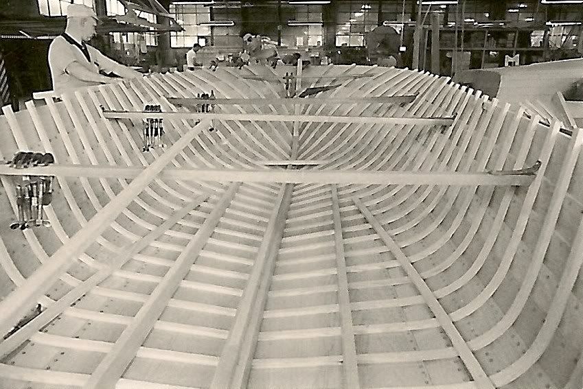
See that hump at the outer edge of the garboard plank near the transom? Facing forward, it's a bit tougher to capture on camera, but look at this:

Image

All the frames through the midsection seem to be crowned... concave on the bottom, laterally, between the floor risers (outermost longitudinal member) and the keel. On the transom, there is a straight line from the turn of the bilge to the keel. Should it be any different as you move forward, or should that continue to be a straight line, albeit possibly with a changing slope/deadrise?

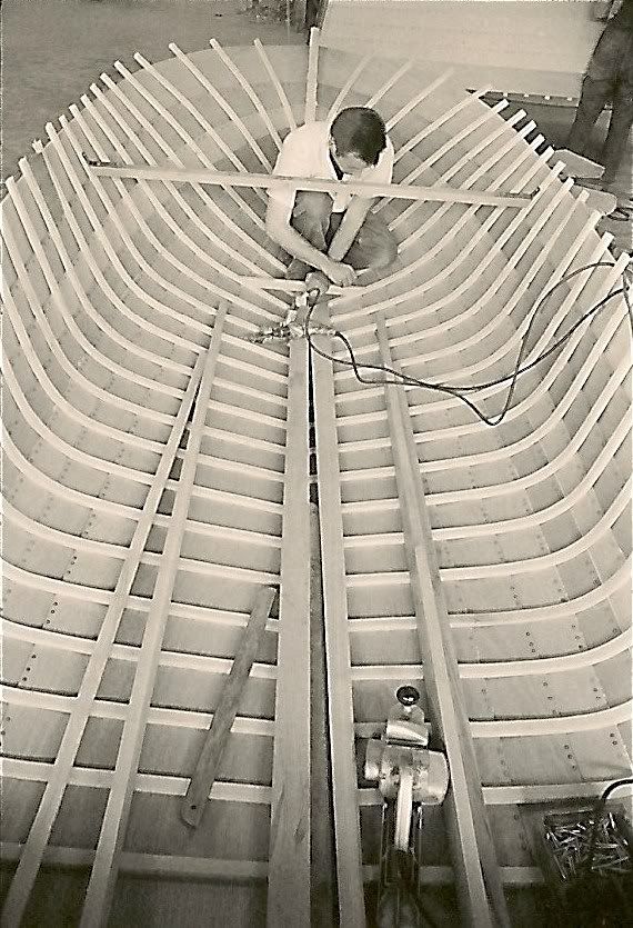
As much as I love having gotten an almost new trailer with the boat, I think it might be partially to blame. The bunks do not sit under the stringers/AKA sister keelsons, but rather to the outside of them, just below the joint between the garboard and the first narrow plank. Here's my assessment of what that's doing:

Image
Image

As discussed under the other topic, the flooring isn't necessarily supposed to be flat laterally on a Peshtigo model, but look back at that photo with the level in it... the floor riser is a good 1.5" below the plane formed by the sister keelsons. Isn't that excessive? It also seems to be lower on the starboard side than on port. I've lightened up the boat enough that I can lift the transom slightly, and it appears that some of this crowned effect goes away when the boat is not resting fully on the trailer.

I just want to make sure that I restore the boat's intended shape while I'm restoring the structure. Otherwise, I'm going to have a boat that's structurally sound, but a poor (or unsafe) performer. I guess it comes down to these facts and the following conclusion: Since the transom has a straight line from the turn of the bilge to the keel, and since a planing hull is supposed to be straight longitudinally in the rear portion (say, ~5' here), I'm guessing that the frames should be straight (laterally) between the bend and the keel, and also at a constant deadrise angle. Is that right? Does that make sense? I'm just putting that two + two together as I write....

Finally, if the trailer is at least partially at fault, it should be a simple matter to unbolt and reposition the bunks to lie directly under the sister keelsons. I may want a second set of guides/bunks farther out if I do that, just so the boat won't be tippy when sitting on the trailer.

Again, any and all thoughts & advice are greatly appreciated. I'm trying to move forward on this as quickly as possible!

-wte
Image
Bill Eason
Atlanta, GA
LancerBoy
Posts: 1417
Joined: Mon Jan 28, 2008 3:47 am
Location: Minneapolis

Post by LancerBoy »

Hi Bill,When it warms up a bit (it's negative 14 F again this morning) I will go out and look at my '57 Peshtigo Sea Lancer. I do not think the floor support along the hull should be 1 1/2 inches below the sister keelsons.I also think that your trailer could be causing some of the problem. I suggest, as you concluded, getting the bunks under the sister keelsons.Andreas
Bill E
Posts: 71
Joined: Fri Jan 11, 2008 7:02 pm
Location: Atlanta, GA USA

Post by Bill E »

<begin tongue-in-cheek mode>
Oh, for the love of boats, Andreas! Don't be such a wuss! Get out there and get me some measurements. I need hard data, and I don't just mean frozen solid in the middle of winter hard data.
<end>

Seriously, on days like this in Atlanta (62.5 degrees & sunny), it's easy sometimes to forget that others don't have it quite the same. I've been on forums in the past with Aussies and New Zealanders talking about sailing in January. Kinda breaks us out of our little boxes to think about it sometimes.... :-)

That said, I'm getting more comfortable with the conclusion I reached last night regarding frame shapes. I have to think in 3-D to put it together, but it seems that's the only way to get a good planing surface, with no hooks in the bottom.
Image
Bill Eason
Atlanta, GA
HalcyonDays
Posts: 83
Joined: Tue Jan 22, 2008 6:09 am

Post by HalcyonDays »

Hi, read your problem and wondered if your trailer has any support under the keel? It would seem to me that moving the bunks in toward the center of the boat would make matters worse. But then again I don't pretend to know what I am talking about.

My boat while it is on the trailer; the floor board are supported by the sister keelsons, if anyone were to get in the boat all of their weight would transfer to this area and cause the problems that you discribe. I think that the keel should take the majority of the weight of the boat; support under the sister keelsons to steady the boat and provide support for anything ie. people or gear that is on the floor; a set of bunks further out if more steadyness is needed. Most boats I see out of water have the keel taking all the weight with jackstands placed to steady the boat.

I will be interested in hearing what people have to say. I am in the process of putting bunks on my trailer. My plan was to have the keel supports continue to take the weight the bunks high enough to hold its shape, but not so high as to take the weight away from the keel.
Bill E
Posts: 71
Joined: Fri Jan 11, 2008 7:02 pm
Location: Atlanta, GA USA

Post by Bill E »

Good point. No, there's no support under the keel, except for a single roller that probably bears no weight, up at the stem. A bunk down the center should probably be added to bear most of the weight. However - and I can't remember if I read this on this forum or in one of Danenberg's books that I just received - the kind of support you mention with the keel bearing the weight and some jack stands propping up the sides is really only appropriate for traditional full-keeled ballasted sailboat-type hulls, not hulls like ours.

Reading back over Danenberg's Vol 2 chapter 12 on trailers just now, he says the most important bunks are the ones under the bilge stringers (in our case, the "sister keelsons"). This is especially important for inboard motorboats where those members are carrying the weight of the engine. Secondary bunks should be at the chine, or the turn of the bilge. These will help to steady the boat and support the weight of people resting on the boat's sides. Third, and optional, but advisable, is the keel bunk. Interesting.

-wte
Image
Bill Eason
Atlanta, GA
john
Posts: 261
Joined: Tue Dec 27, 2005 7:33 pm
Location: Crosby (Houston) Texas
Contact:

Post by john »

It can be brought back.

Assumptions.

1. Sky side of inner keel, and sisters were straight as built.

2. Sky side of deck was in a straight line as manufactured? If not the contour should be easy to measure off a good existing boat.

3. The sides of the hull are most likely are in the same shape as when built. I'm assuming this as there in little rot above floor.

4. The shape of the hull from the dash forward is most likely in the same geometric shape as built. It is basically a triangle and even if rotten, it would take a lot to make it change shape.

5. Transom even if very rotten is in same geometric shape as built.

6. Most if not all of deflection is at or below the meeting of sides and bottom.

7. The hopefully the know points are, flat deck, transom, and intersection of inner keel at forefoot (stem)

8. The unknow is the location of the forward end of stringers. Could be dtermined from exsisting boats if found.

Solution:

1. Flip boat and support deck on a straight surface, could be blocks or stringers.

2. Remove all planking on bottom to were it meets sides.

3. Duplicate new inner keel using old one as pattern, top of original inner keel was most likely straight, so use old inner keel as a pattern for off sets only. I would and did on my 202 increase inner keel size to a xsection of 5"x6" way bigger than stock.

4. Same for both outside stringers.

5. Screw but not glue new inner keel in place between transom and keelsom.

6. As JOECB says use inner keel as ridge.

7. Screw but not glue stringers to transom, THE QUESTION is where to position their forward end? A dimension from a good boat from the deck to floor could determine this, many measurements from several boats. After that it's eye ball time.

8. Having an end point ( the inner keel ) and a stringer to bend around, you should be able to shape new ribs by steaming.

9. After forming and fashening new ribs in place, I would carefully remove transom and rework or replace as required.

10. After transom I would remove enough lapstrakes on one side to be rework/ replace stem and forefoot.

12. After new/reworked stem is in place, I would reattach the old lapstrapes if possible. New ones if required, using old as patterns. I would stripe and CPES and varnish all wood old or new before reattaching. This gives protection the boat never had before as the back sides of framing were never coated.

13. After the one side is complete I would do the other, but this time starting from the keel with new garwood or reworked old if possible.

14. Forgot to glue and screw, after fit up.

15. Use 3M 5200 between lapstrakes and expoxy from stem,keel, and transom built up.

16. Many parts that are not rotten could be lightly run thru thickness planner to remove paint to bare wood.

17. Be certain inner keel and striger are flate within 5' of transom forward within a 1/16", float as required. In front of that point make sure keel is either straight or has a rocker as orginal keel did.

Should work! Any thoughts about process or assumptions???????????
Out of Time will continue
Last edited by john on Mon Feb 11, 2008 5:46 pm, edited 4 times in total.
JoeCB
Posts: 241
Joined: Fri Dec 30, 2005 5:17 pm
Location: Farmington Hills , MI

Post by JoeCB »

From my expierence with my 57' Sea Lancer , John is correct. If you flip the hull and fit a straight keelson (with side cheeks) from the transom to the end of the stem the ribs can be laid in just like a carpenter laying in rafters up to a ridge board. The ribs are straight ( flat) from the turn at the chine out to the keelson.
As a suggestion, there is an oppertunity to strenghten the keelson to stem joint by extending widened cheeks beyond joint and fastening to the stem piece. The original design had the cheeks tapered to almist nothing at this joint.
Joe B
Bill E
Posts: 71
Joined: Fri Jan 11, 2008 7:02 pm
Location: Atlanta, GA USA

Post by Bill E »

Here's the latest discovery on my Sea Lancer's bottom shape. Apparently, years of hanging a heavy outboard on the transom have had their effect. When I first saw this boat in 2004, I had noticed that the transom had pulled away from the quarter knees as shown in this photo:

Image

What I've determined today is the effect it has had elsewhere in the boat, particularly on the bottom. As this diagram shows, the transom has those aluminum straps that run down to the sister keelsons in place of a standard transom knee to the keel(son). I put an 8' straightedge on the sister keelson, and it seems that the downward/backward force of the motor has lifted the sister keelsons a fair amount (or dropped the tail ends of them), introducing a hook in the rear portion of the bottom.

Image

What I can't yet explain is the major downward bend in the sister keelsons toward the front. Maybe my future forensics will shed some light on that part.

NOW, MY QUESTIONS!
1. I just wanted to make sure that the sister keelsons are supposed to be straight, just like the center keelson itself.

2. Given that I'm not planning to change out the motor, how can I help prevent this same effect from occurring again? Granted, it's taken 50 years to get to this point, although I know the boat didn't have this 1978 motor for its first two decades. Maybe some other heavy hulk, but not this one.

Here are my initial thoughts on the matter:
Given: The sister keelson bent around the point where the brackets attach. Stiffening from that point back alone will do nothing.
Given: The sister keelson is acting as a beam to resist this bending force.
Given: It's easier to gain stiffness by making the beam taller rather than thicker.
Given: The plywood sole starts just ahead of this pivot point, so without modifying the sole, I can't make the sister keelson taller.
Given: It's a lot easier to thicken the sister keelson than to make it taller.
Given: You can also gain stiffness by using a stiffer material.

My initial solution, then, is to add a flitch plate of sorts. Maybe a 1/4" bronze plate around 4' long, sistered up against the sister keelson from the transom forward, and screwed or bolted to it in several places along its length. I don't see that it would need to be sandwiched between two pieces of wood, would it? Naturally, I'd seal the adjacent wood, maybe bed it to the metal, etc., but how does this sound for a solution? Any suggestions for alternatives?

The other point is that the transom has obviously bowed out from the weight of the motor. I think that fixing the bottom stiffness & straightness would help greatly in preventing the transom from bowing, but do I need more? Like a bigger/stronger oak stiffener across the inside of the transom? Just curious what others have done, and whether I'm overkilling or overengineering.

Thanks,

-wte
Image
Bill Eason
Atlanta, GA
LancerBoy
Posts: 1417
Joined: Mon Jan 28, 2008 3:47 am
Location: Minneapolis

Post by LancerBoy »

Here's a picture from the Thompson Bros. Boat Mfg. Co. factory at Peshtigo, WI in the early 1960s. Just to give you some idea of what the hull looked like during construction.

Image

Andreas
LancerBoy
Posts: 1417
Joined: Mon Jan 28, 2008 3:47 am
Location: Minneapolis

Post by LancerBoy »

One more picture from the Peshtigo Thompson Boat factory in the early 1960s.

Image

Andreas
Bill E
Posts: 71
Joined: Fri Jan 11, 2008 7:02 pm
Location: Atlanta, GA USA

Post by Bill E »

Andreas - those are awesome! From what I can tell in those photos on that model, the keelson and sister keelsons are dead straight, dead flat for their full lengths.

Just curious - in the second photo, near the bottom, is that an early power planer? I can't imagine what else would be shaped like that... I didn't know they had them back then, but a quick Google search shows that they were beginning to appear from Rockwell/Porter Cable.

-wte
Last edited by Bill E on Thu Feb 21, 2008 6:12 am, edited 1 time in total.
Image
Bill Eason
Atlanta, GA
LancerBoy
Posts: 1417
Joined: Mon Jan 28, 2008 3:47 am
Location: Minneapolis

Post by LancerBoy »

Yup, my guess is that it's a power planer.

Andreas
Post Reply